Back to Basics – Measuring Return Loss
The following is a re-post of a popular past blog post that explains the basics of return loss, why it’s an important measurement, and technologies for measuring return loss.
Fiber optic networks span a wide range of lengths. Intercity and transoceanic fiber optic telecommunications networks span thousands of kilometers. In aircrafts and ships, telecommunications systems have link lengths up to 500m. Data center networks have lengths on the order of meters. Finally fiber optic components have very short lengths on the centimeter and smaller scale.
在所有这些应用程序中,数据需要以极高的保真度从源发送到接收器。沿途发生的任何丢失或反射事件都将导致信号退化。这篇博文旨在概述光学回波损耗(RL)的潜在来源以及测量它的重要性。
Definition of Return Loss
在技术术语中,RL是被测设备反射回来的光的比率,Pout, to the light launched into that device, Pin,通常表示为负数,单位为dB。
RL = 10 log10(Pout/ Pin)
Sources of loss include reflections and scattering along the fiber network. A typical RL value for an Angled Physical Contact (APC) connector is about -55dB, while the RL from an open flat polish to air is typically about -14dB. High RL is a large concern in high bitrate digital or analog single mode systems and is also an indication of a potential failure point, or compromise, in any optical network.
What Does High Return Loss Indicate?
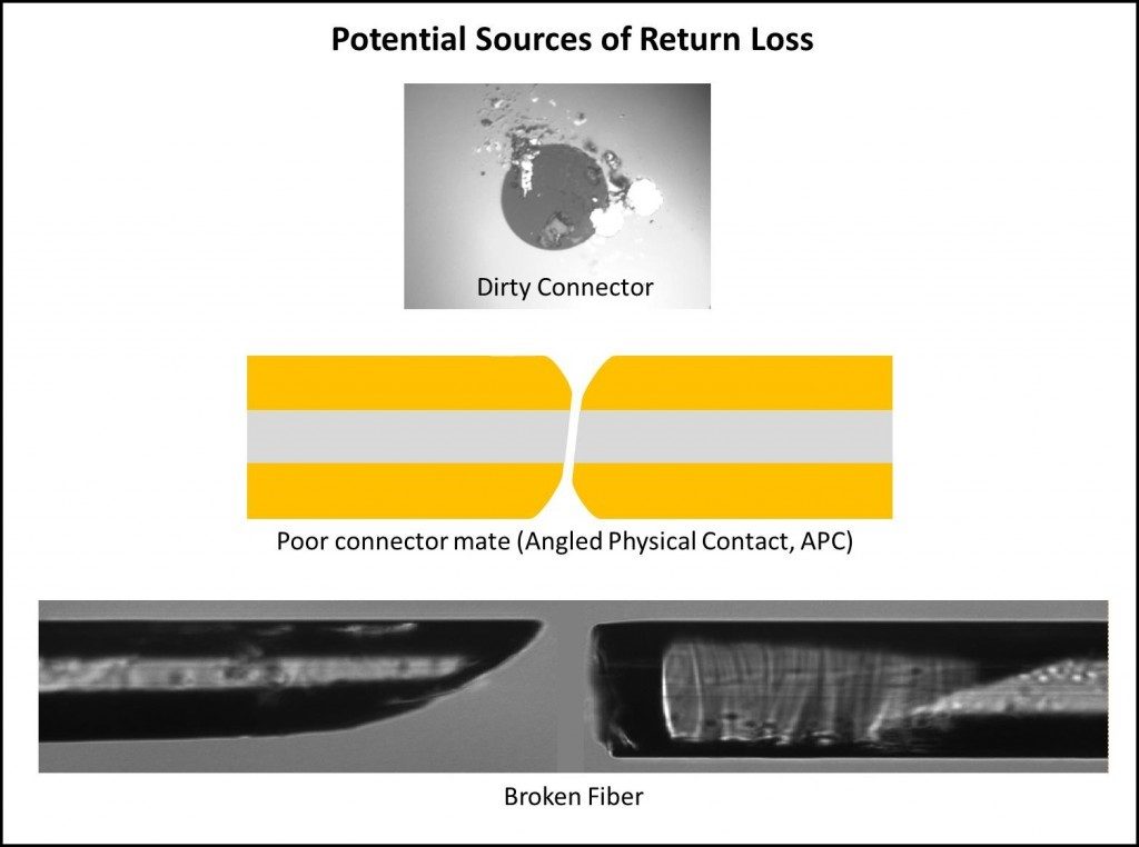
Dirty Connector
光网络中有一些非常简单的故障会导致高RL。一个脏的连接器就是这样一个来源。即使是5微米单模磁芯上的微小尘埃粒子,最终也会阻塞光信号,导致信号丢失。
Broken Optical Fiber
A break in the optical fiber can also cause high RL. In some instances, it is possible for the optical fiber to have a break in it, but still be able to guide light through. In this case, a measurement of insertion loss (IL) across this fiber will result in a low IL. This disguises the extent of the problem where a direct RL measurement would immediately highlight it. In addition, a crack in a fiber can have both low IL and low RL and easily be missed as a problem in the system. However, a sensitive RL measurement will show a reflection peak where there should be none, indicating a crack in the fiber that will likely lead to failure.
接头配合不良
如果连接器未完全就位,连接器端面之间产生的气隙将导致从该点开始的高RL。在这种情况下,IL可能较低并且信号保真度可能仍然良好。然而,这将是一个令人担忧的问题,因为这种松散的连接现在是一个可能的故障源,因为它可能会在服务时错位或完全断开。
产生多径干扰并降低信号质量
Multiple high reflection points within a network can lead to the optical effect known as multipath interference. This interference can easily lead to signal degradation, especially in high speed networks. In addition, many fiber optic transmission systems use lasers to transmit signals over optical fiber. High RL can cause undesirable feedback into the laser cavity which can also lead to signal degradation.
回波损耗测量方法
There are three established reflectometry techniques used for measuring RL as a function of location along an optical fiber assembly or network: optical time domain reflectometry (OTDR), optical low coherence reflectometry (OLCR) and optical frequency domain reflectometry (OFDR). The different methods have tradeoffs in range, resolution, speed, sensitivity and accuracy. Typically, the low coherence technique is used for sub-millimeter resolution measurements over a limited range (< 5 m). OTDR is typically used for long range (several kilometers) measurements with low spatial resolution.
卢娜的OFDR
OFDR, the technology used in ourOBR公司product line, is ideal for measurements from the component level to short networks (up to 2 km). OFDR produces measurements with spatial resolutions as fine as 10 microns over 30 m or a few mm over 2 km. This high spatial resolution measurement over intermediate lengths can provide significant advantages. For example, when an OBR is used to troubleshoot a network on an aircraft it is able to very precisely pinpoint the location of a fault, so that a technician knows which panel to open or on which side of a connector the fault was located. The sensitivity of OFDR also makes it possible to detect small RL events such as cracks that would be difficult to detect with other methods, but could lead to in-service failures.
Learn more aboutOBR公司high-resolution reflectometers.