嵌入式传感器可以检测损伤的复合材料
将非常高的强度与重量轻,复合材料在航空航天和汽车行业内的越来越多的结构和化妆品。bobapp综合体育下载bobapp综合体育下载随着综合使用在整个行业中生长,需要有效且有效的非视损伤检测方法。bobapp综合体育下载为了满足这种需求,Luna已经证明,掺入碳纤维复合试验制品中的高空间分辨率(0.65mm)光学菌株传感器可以通过测量应变型材的变化来有效地检测影响损伤,即使冲击导致纤维骨折和可见表面下方的分层。
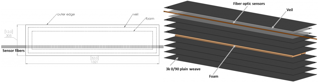
To test this method, a mock aircraft skin panel was fabricated to assess the distance over which the damage imparted to the panel propagates. The panel was fabricated from eight plies of 193 g/m23K plain weave fabric with a 19 mm foam core on the mid-plane. Optical fibers were embedded just below the outermost ply in three parallel passes spaced 1 cm apart.
The panel was then impacted to determine the relationship between fiber to impact distance and the strength of the induced fiber signal. A drop style impactor, similar to that which is used in ASTM D7136, was utilized to impart a quantifiable and controlled series of impacts. Strain measurements were achieved using Luna’sODiSI systemfor high-definition fiber optic sensing (HD-FOS).
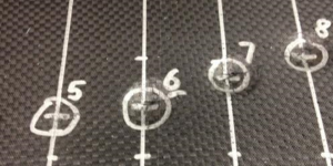
The following figure diagrams the location of 16 impacts. The initial eight impact events were conducted with the same impact parameters. The next six impacts (9-14) were spaced at larger horizontal spacing, and with less energy, to avoid conflating the results of the various impacts. Two final impacts were made at locations 15 and 16 between the bottom two fiber sections, to determine whether especially close proximity between the impact and the fiber altered the response.

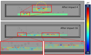
The following figure displays strain as a color map on a drawing of the panel after the 4thand 16thimpact. Impact site 4 shows successively decreasing levels of strain propagating outwards from the impact location. The yellow circle traces the region of damage based on the reported strain. Note that the center of the circle is almost exactly over the impact location. The lower portion of the figure shows the cumulative damage resulting from all impacts performed on the impact panel. It is obvious that all impact events within ~5 cm of the fibers have resulted in a clearly discernible response in the strain profiles.
This research was partially funded by NASA through a Phase I SBIR. A paper on this work was published at the Composites and Advanced Materials Expo 2017, December 11-14, 2017. The full reference for the paper is:
Kominsky, Daniel., Rahim, Nur Aida Abdul., Davis, Matthew,. Garg, Naman., Castellucci, Matthew., Bryson, Reginald., Beaty, Noah., "Extracting Information from Damaged Carbon Fiber Composites Using High Definition Fiber Optic Sensing (HD-FOS)." Composites and Advanced Materials Expo 2017, December 11-14, 2017
有关Luna Odisi测量系统有助于加速复合材料的其他方式的更多信息,请参阅此简短应用简报High Definition Strain Sensing for Composites with HD-FOS.